NAS assembly in CI Hex Viewer
NAS (Network Attached Storage) is a complex stand-alone device that allows not only storing but also sharing data inside a local network. NASes may contain more than one disk under one cover. Generally, multiple-disk devices base on a RAID configuration putting all their components into one solid system applying a special data organization scheme. If the entire system happens to fail, you get it disassembled into a set of separate disks. Any operations on the storage data won't make any sense unless the storage is re-assembled. Facing a task of data recovery from NAS, you need the information about the order of NAS drives, RAID level and its distribution algorithm. If you have those details and you are sure about their reliability, the task is simplified. But in case of no such details the disk contents analysis is almost the only solution. By an example of a virtual NAS storage, we would like to show some tips for analyzing data from a NAS device. The CI Hex Viewer software is used for this analysis. |

Load NAS disks
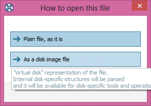
First, we open all virtual NAS disks in CI Hex Viewer as disk images to make them available for internal RAID-Builder tool. To do this we press Open, select File and open all virtual disk as a disk image file.

Open NAS disks into RAID Builder
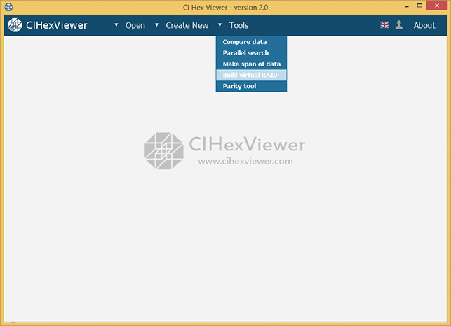
First, we open RAID-Builder itself. To do this we press Tools and select Build virtual RAID from the drop-down list.
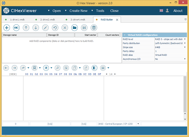
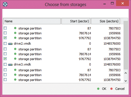
After that, we add all virtual disks into the tool. To do this we press Add component in the RAID-Builder tool bar and select the disks opened in the program from the dialog window.
NAS is specific in that it has three equal partitions on each disk: firmware partition, swap partition and data partition. We'll need only data partition to build RAID configuration. Data partition is easy to define – it's the largest in the raw.

Set RAID parameters
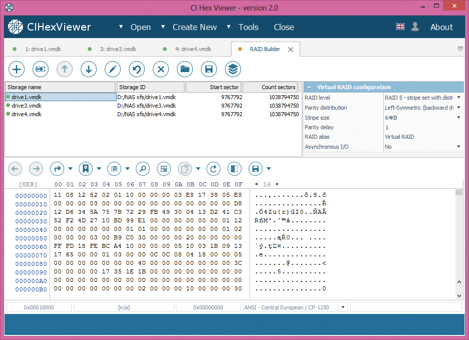
In our example, we have left-symmetric RAID 5 with 64 KB stipe size, one missing drive, and messed-up drives order.
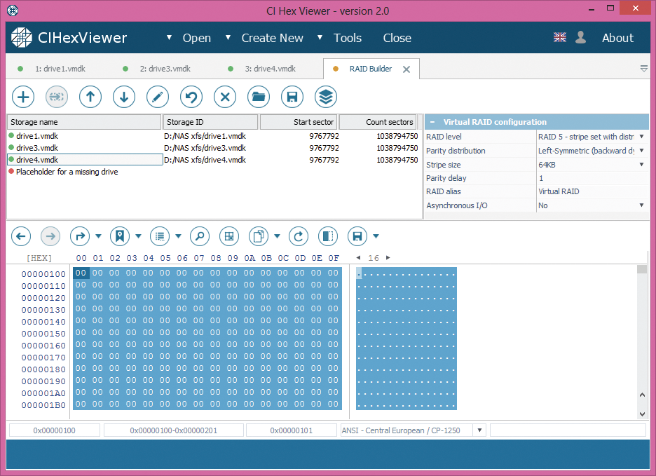
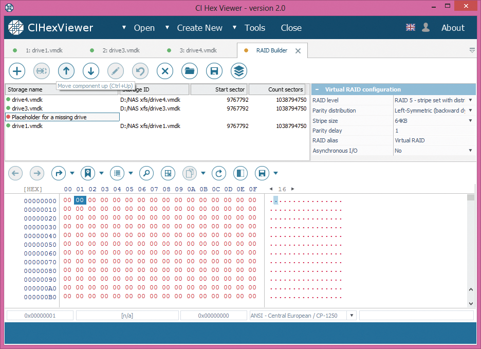
With all that information, we set parameters for the virtual RAID configuration. We choose RAID5 as RAID level, left-symmetric for Parity distribution, 64KB as Stripe size, 1 for Parity delay, we name the assembled storage as RAID NAS and select when possible in the asynchronous I/O to speed up work with the assembled storage in the program.
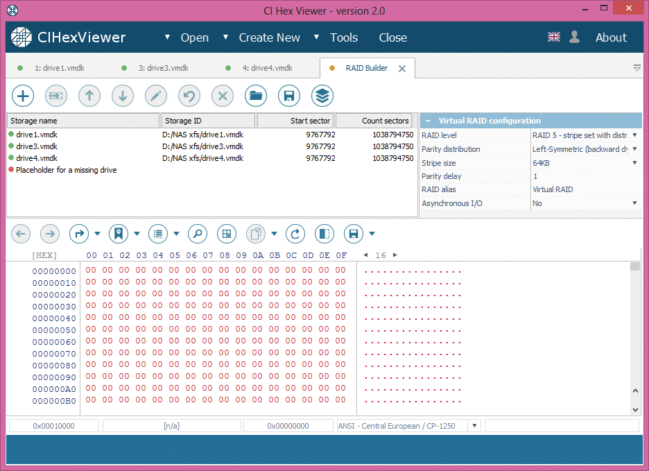
For RAID 5 it is possible to reconstruct the system operation without one disk. To make the configuration complete, we add a placeholder for the missing drive.

Check configuration
RAID 5 has the following distinguishing marks:
-
Only the first block contains superblock.
-
In RAID 5 layouts with default 64KB stripe size, inodes block locates at zero offset of a data partition of the second drive. The first inode indicates a directory (root directory).
-
Start block of the third drive contains data or inodes table.
-
Start block of the fourth drive contains parity.
-
If XOR operation is applied to any bytes from the start blocks of each disk at the same byte position, you will always get zero result.
Drives order is as follows: drive with superblock – the first; drive with root directory – the second; drive with parity – the fourth; remaining drive – the third.
Now, let's check this information:
-
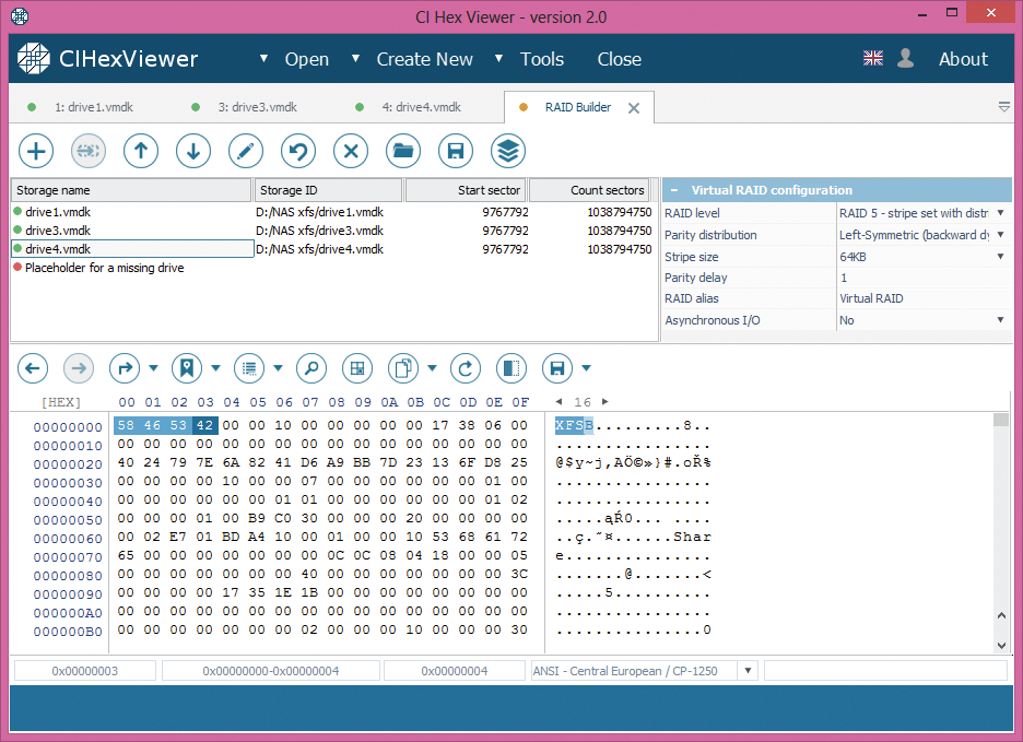
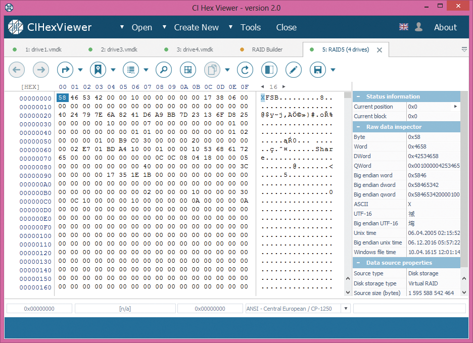
The analysis of the fourth drive shows that it contains a valid XFS superblock. The basic signs of XFS superblock are 'XFSB' string at the start, file system parameters and zero values in a range from 0x100 to 0x200.
-
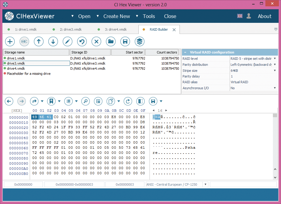
Inodes, typical of Unix-like file systems including XFS, are small blocks sized 256 bytes containing technical information (metadata) about objects - files and folders. This information can include user and group accounts, access mode (read, write, execute permissions), type, file names etc. Being not exactly the data, they only point to actual object location. Each object in such a system has its own inode. Inodes can be identified by 'IN' string ('49 4E' byte sequence) at the start of each 256th (0x100) byte. The upper digit of the third byte from the inode start defines an object type: byte “4…” indicates a directory, and byte “8…” – a file.
In our example, Disk 3 contains inodes table, the first inode is a pointer to the root directory.
-
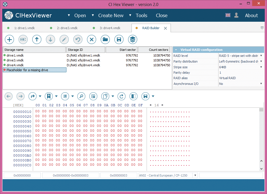
Start block of the third drive 0 contains data or inodes table. In our example, we only have one drive left and it doesn't contain any data information or inodes. So, we assume that failed drive stood on the third place. In this case, we put the placeholder to the third drive's place.
-
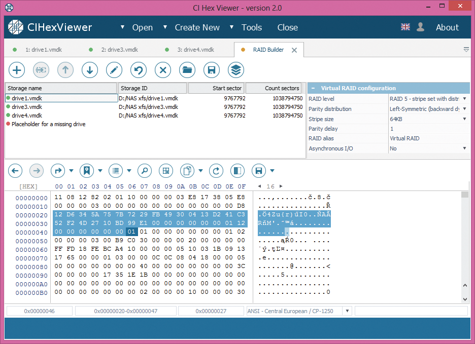
Parity block contains a mixture of the data from data blocks of other drives. It may look like 'garbage' with fragments of data from data blocks.
Even if the parity disk has a valid 'XFSB' string as the superblock, it also has non-zero data at a range from 0x100 to 0x200 bytes making it different from the superblock. Compared to the superblock, parity block usually has more non-zero byte values.

How to check parity:
-
Choose partition offset with non-zero data.
-
Run calculator (e.g. Windows standard calculator).
-
Choose 'View' as 'Scientific' or 'Programming', switch the mode from 'Dec' to 'Hex'.
-
Type a hexadecimal digit from the first drive, press 'Xor' button.
-
Type a hexadecimal digit from the next drive at exactly the same offset and press 'Xor' again.
-
Repeat until the last drive. Before you enter the digit from the last drive, the calculator must show the same number as at specified position of the last disk. The last 'Xor' operation will give zero. Non-zero value indicates either calculation error or parity absence.
According to our analysis, we set the drives as follows:
Drive 4 – superblock – the first
Drive 3 – inodes – the second
Placeholder – the third
Drive 1 – parity – the fourth

Assemble RAID
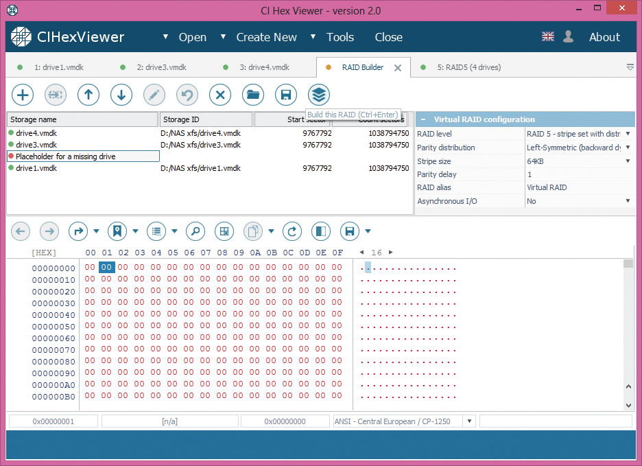
Pressing “Build RAID” we assemble virtual RAID system for our NAS to handle it further on as a solid data storage.
Summary:
if a NAS device fails for some reason, before proceeding to any further operations you should assemble the RAID configuration that this NAS storage was based on. For assembly of the RAID configuration you need to know RAID parameters or find them out by means of a detailed data analysis. CI Hex Viewer allows easy analysis of the data on the disks of the NAS device as well as for a simple further assembly of its RAID.